- #HOW TO ADD PROBE PSPICE SCHEMATICS HOW TO#
- #HOW TO ADD PROBE PSPICE SCHEMATICS SOFTWARE#
- #HOW TO ADD PROBE PSPICE SCHEMATICS FREE#
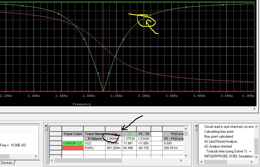
Select Tools/label/Mark to label the cursor coordinates directly. Using left mouse button or right mouse button to select the cursor, One cursor is selected by left mouse button and the other cursor is selected by right mouse button. Select Tools/Cursor/Display to add cursors on the plot.Ī probe cursor box will appear. Starting Simulation Outside of Schematics. Select Tools/Label/Text to add text label. Additional marks of MicroSim include: StmEd, Stimulus Editor, Probe, Parts, Monte Carlo, Analog. Select Plot/X-Axis settings or double-click on the x-axis to change the X-Axis settings.

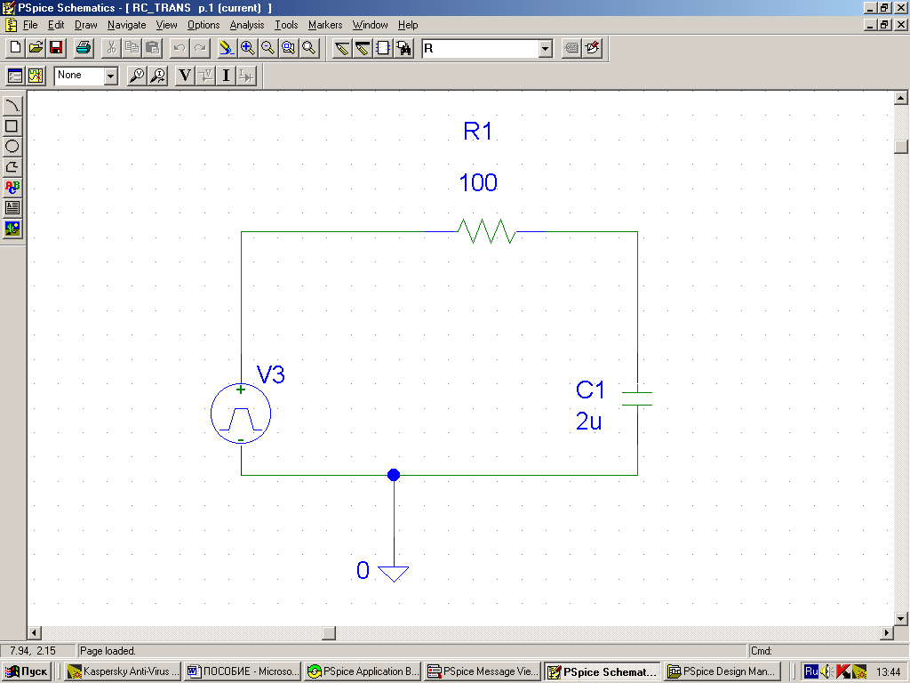
Select the add Library Icon in the Place Part Pop-up menu. Adding libraries If you are using PSPICE for the first time on your computer or you are using a lab computer, the parts libraries will need to be added. Add ports to the schematic, which will serve as the leads of the transformer. Once you have clicked OK in the Create PSPICE Project dialog box, the schematic window will open and you are ready to begin adding libraries.

Select Plot/Y-Axis settings or double-click on the y-axis to change the Y-Axis settings. Demo Version: Start Cadence- OrCAD 16.5 Lite OrCAD Capture CIS Lite. From: Analog Design and Simulation using OrCAD Capture and PSpice, 2012. Select Edit/Modify Title to modify the title. Or in the Trace Expression, type name of the expression.
#HOW TO ADD PROBE PSPICE SCHEMATICS SOFTWARE#
When voltage or current markers were marked in the schematic, the plot will automatically display. The software is used mainly by electronic design engineers and electronic technicians to create electronic schematics, perform mixed-signal simulation and. Circuit 1 represents a simple sample of a DC circuit with a voltage source and four resistors. Here we will be using the circuit 1 as a reference. CIR input file is to draw the schematic figure of the circuit to be tested. In Probe, you can visually analyze and interactively manipulate the waveform data produced by circuit simulation. The first thing to do before writing a PSpice. Once you have clicked OK in the Create PSPICE Project dialog box, the schematic window will open and you are ready to begin adding libraries. MicroSim Probe is the waveform analyzer for Pspice simulations. choose which type of project you want to create. Message window will automatically open during simulation. And the Probe will automatically open and all of the value of marker will appear on the plot. Select Analysis/Simulate or click on the simulate icon to run simulation.Īfter simulation, the DC values of voltage and current can be displayed when using DC bias point analysis. Select the appropriate command file (you can have created more than one for one simulation, of course) and.Determines the output affected from the tolerances of the components. (or do nothing, it's up to you).Ī) Start with an empty Probe window (don't use any probes within the schematic diagram)ī) Use PSpice Probe Menu/ File/ Run Commands. So, when you comprehend the principle by exploring the recorded commands in that file (it's quite easy), you can do "whatever you want" with them (what is allowed, of course -), add some new by hand, etc. response study because PSpice assumes it is in the time domain, and therefore your probe.
#HOW TO ADD PROBE PSPICE SCHEMATICS FREE#
(using the same menu item as before).ĭuring the recording you can insert required traces, make calculations with trace variables, insert new plots, etc.Īfter that (when recording has been stopped), the recorded commands can also be edited in a (" pure") text editor. pspice square wave 1 Free Electrical Schematic Diagram Software. Powerup to unlock perks for r/ECE Become a Hero. A subreddit for discussion of all things electrical and computer engineering.

#HOW TO ADD PROBE PSPICE SCHEMATICS HOW TO#
Its default extension is cmd but it's a text (macro) file.įrom this time on all commands are recorded in the above file unless you stop it by: This page shows how to add new models and libraries to your Pspice installation. Use PSpice Probe Menu/ File/ Log Commands.Ĭhoose a directory and a name for a command file. This problem can be solved (in PSpice) using command file(s) the following way:Īfter a simulation delete all traces in the Probe window (don't use any probes within the simulated circuit schematic the Probe window is empty then)

maybe it's too late, but what if it can still help. I was browsing the unanswered questions like Vlad did (see the comment above), so.


 0 kommentar(er)
